
Introduction
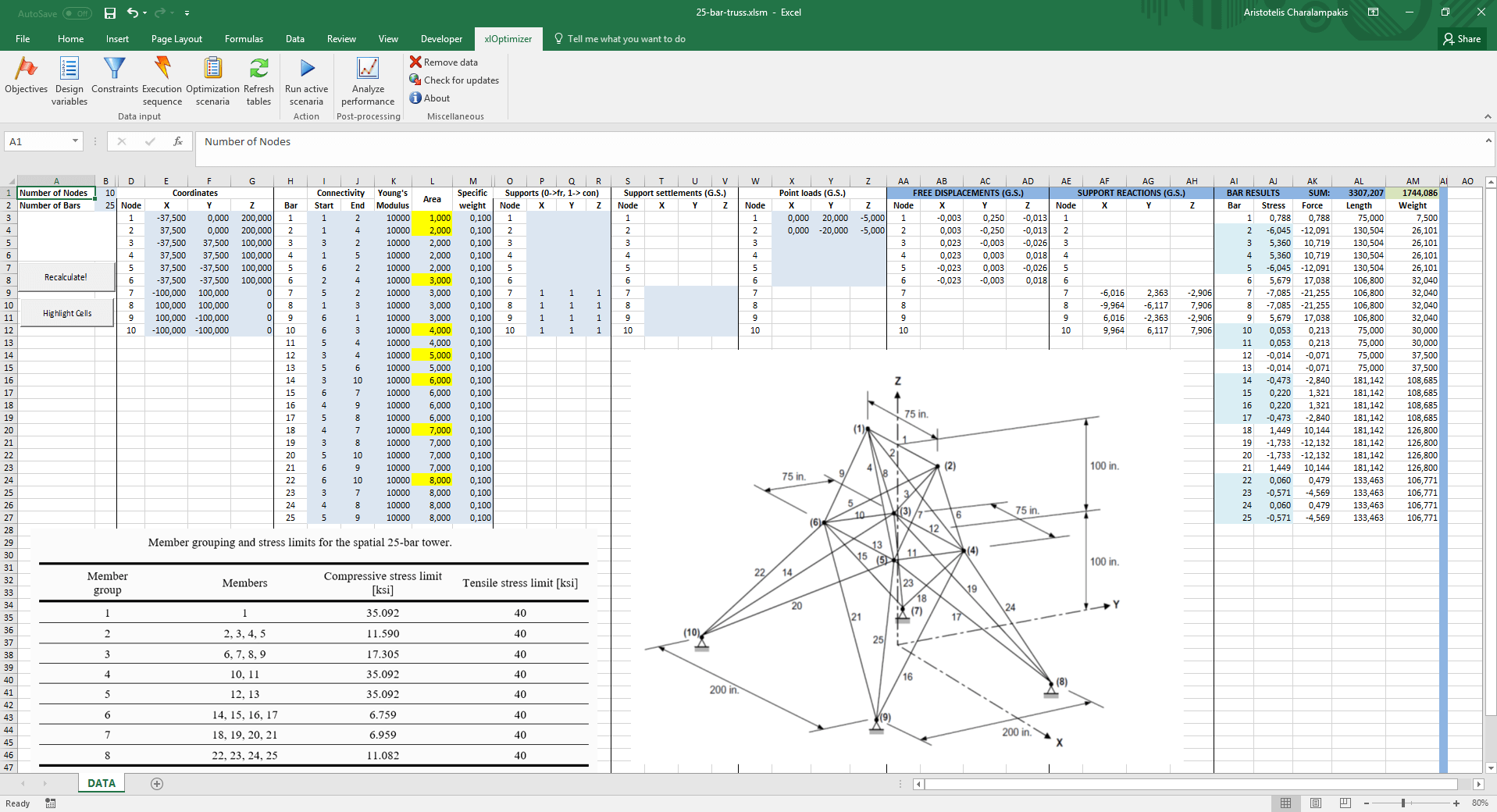
The purpose of this example is the minimization of the weight of a space bar truss. We will use a well-known benchmark problem, i.e. the 25-bar space truss, which has been studied extensively in the literature. The geometrical data is given in the picture (in inches). Although there are 25 bars in the truss, these are grouped into 8 groups, according to a table given below, which makes the problem easier (i.e. it reduces the problem's dimensionality from 25 to 8). The material's Young's modulus is E = 10000 ksi and the specific weight is ρ = 0.1 lb/in3.
The purpose is to minimize its weight by picking the appropriate cross-sectional area for each bar, so that the following requirements (constraints) are met:
- The cross-sectional area of each bar varies between 0.01 and 35 in2 (these are the so-called side constraints of our design variables)
- The stress in each bar does not exceed a certain tensile and compressive level, given in a table below
- The displacement of the top nodes (1,2) in each direction should not exceed 0.35 inches
The table with the bar grouping and stress levers is the following:
The table with the bar grouping and stress levers is the following:
| Member group | Members | Compressive stress limit [ksi] | Tensile stress limit [ksi] |
| 1 | 1 | 35.092 | 40 |
| 2 | 2, 3, 4, 5 | 11.590 | 40 |
| 3 | 6, 7, 8, 9 | 17.305 | 40 |
| 4 | 10, 11 | 35.092 | 40 |
| 5 | 12, 13 | 35.092 | 40 |
| 6 | 14, 15, 16, 17 | 6.759 | 40 |
| 7 | 18, 19, 20, 21 | 6.959 | 40 |
| 8 | 22, 23, 24, 25 | 11.082 | 40 |
Two load cases are considered, as follows:
| Node | Px [kips] | Py [kips] | Pz [kips] |
| Load Case I | |||
| 1 | 0 | 20 | -5 |
| 2 | 0 | -20 | -5 |
| Load Case II | |||
| 1 | 1 | 10 | -5 |
| 2 | 0 | 10 | -5 |
| 3 | 0.5 | 0 | 0 |
| 6 | 0.5 | 0 | 0 |
Note that there is a difference in this case as compared to the two load cases examined in the 10 bar planar truss. In the 10 bar truss, the two load cases were independent, which means that practically we are dealing with two different optimization problems. Here, the two load cases must be checked for the same configuration. To tackle that we need to write some additional VBA code. The routine Sheet1.Calc solves the current truss configuration and evaluates the displacements and stresses. We have included Sheet1.Calc2, an additional routine which does the following:
- Sets up load case Ι
- Solves the truss using Sheet1.Calc
- Evaluates the penalties for load case I
- Sets up load case II
- Solves (again) the truss using Sheet1.Calc
- Evaluates the penalties for load case II
- Adds the sum of penalties to the weight of the truss.
This routine will be called by xlOptimizer. For demonstration purposes, the constraints will be evaluated by VBA code, so we don't need to include them in xlOptimizer.
Note that solving the same truss twice can be improved considerably, e.g. by not evaluating the stiffness matrix twice, but this exceeds the purpose of this article. Also, this article assumes that you have read and understood the procedures described in the toy problems. These include the optimization using pure Microsoft Excel formulas and the optimization using VBA (Visual Basic for Applications).
Step 1 : Setting-up the spreadsheet
We have already created the spreadsheet for you. It can be used for any space truss. Note that the spreadsheet uses consistent unit system; this means that, if you pick the correct units, you can have the correct results in SI as well. In the file, however, the data has been set in the Imperial System as this was used for the definition of the 25-bar truss. Therefore, the area of each bar is given square inches (in2). The areas of all 25 bars are controlled by 8 bars only, i.e. the first bar in each group (shown in the yellow cells).
The evaluation of the stresses and displacements of the current configuration is performed by a custom routine, i.e. Sheet1.Calc. The code can be inspected if you produce the VBA editor (by pressing Alt+F11).
The function evaluation is performed by another custom routine, i.e. Sheet1.Calc2.
Step 2 : Setting up the objective function
Select cell AM1. This holds our objective function, i.e. the current weight of the truss. In the xlOptimizer ribbon, press Objectives to produce the list of objectives. Then press the Add button '+':
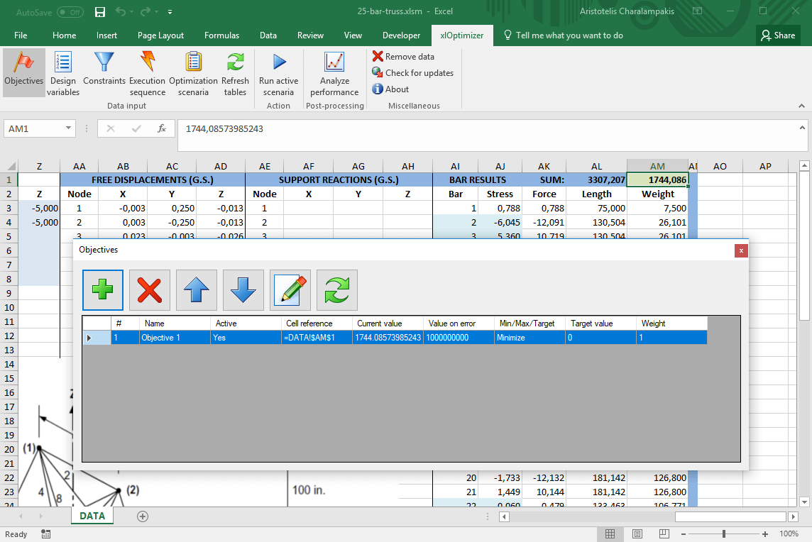
The objective is set to minimization by default. Press the Objectives button in the ribbon again to hide the objectives list.
Step 3 : Setting up the design variables
Select the yellow cells, by holding CTRL and clicking the cells one by one. These hold our design variables, i.e. the cross-sectional area of each bar group. The rest of the bars obtain the same values with simple formulas.
In the xlOptimizer ribbon, press Design variables to produce the list of design variables. Then press the Add button '+' to add the cells to the list:
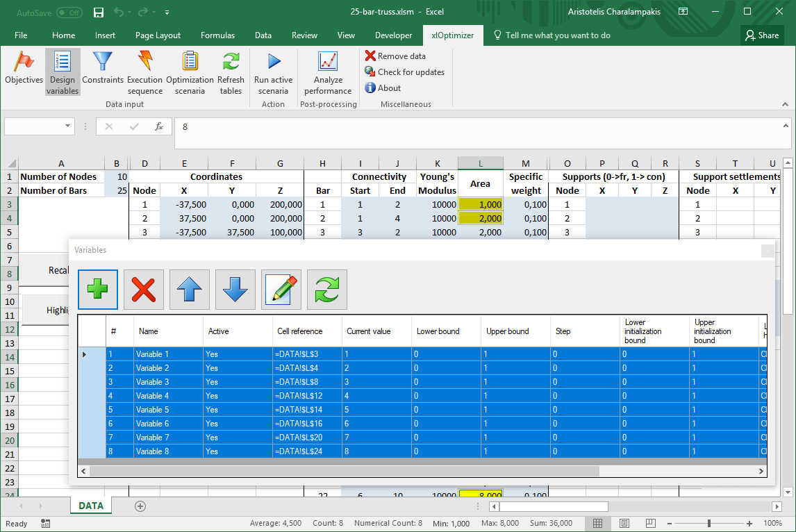
Having all design variables selected in the list, press the Edit button in the toolbar. In the form, set the bounds from 0.1 to 35 and press Ok. The selection will be applied to all selected rows.

Press the Design variables button again in the ribbon to hide the design variable list.
Step 4 : Setting up the constraints
The constraints are evaluated by custom routine Sheet1.Calc2, so you don't need to add them here.
Step 5 : Setting up the execution sequence
In the xlOptimizer ribbon, press Execution sequence to produce the list of execution commands. By default, a single Calculate command is listed. This is a call to Microsoft Excel's internal calculation routine, which evaluates the formulas such as '=SUM(C2:C6)'. Contrary to the 10 bar truss, we need to keep this command, first in the list, because we have used simple formulas to fill in the missing areas for some of the bars, e.g. the area for bar 3 (cell L5) is set equal to the one for bar 2 using the formula '=$L$4'. We must add a second command, which is a macro call to routine Sheet1.Calc2:
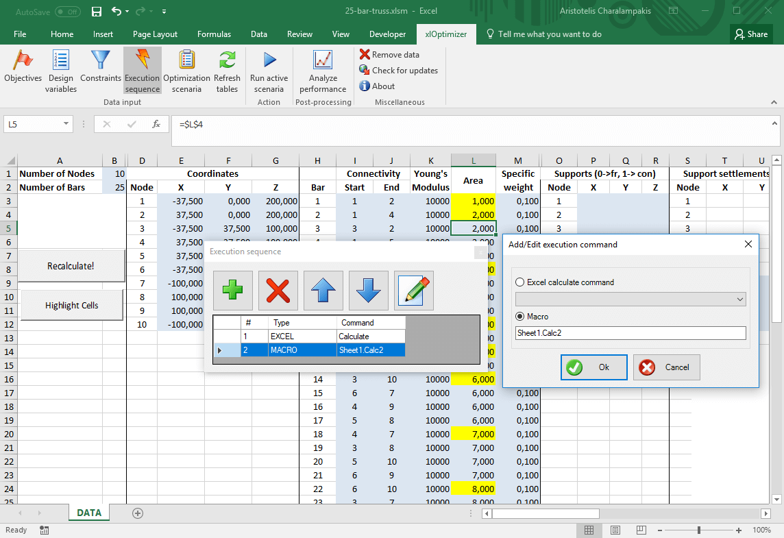
Press Ok to save the changes.
Step 6 : Setting up the optimization scenario
In the ribbon, press the Optimization scenaria button. Next, press the Add button '+' in the toolbar to add a new scenario. The following form appears:

Make the appropriate selections and press Ok. The scenario is added to the list. In this case, the Standard Differential Evolution algorithm was selected.
The data input is now complete. In the ribbon, press the Optimization scenaria button again to hide the list.
Step 7 : Optimization
We can now proceed to the optimization by pressing the Run active scenaria button.
The file for this example can be downloaded here. Note that it is saved a macro enabled book with the extension .xlsm. You need to enable macros to run it.
By inspection of the literature, the best solution for the 25-bar truss that does not violate any constraints has a weight of 545.172 lbs.